|


| |
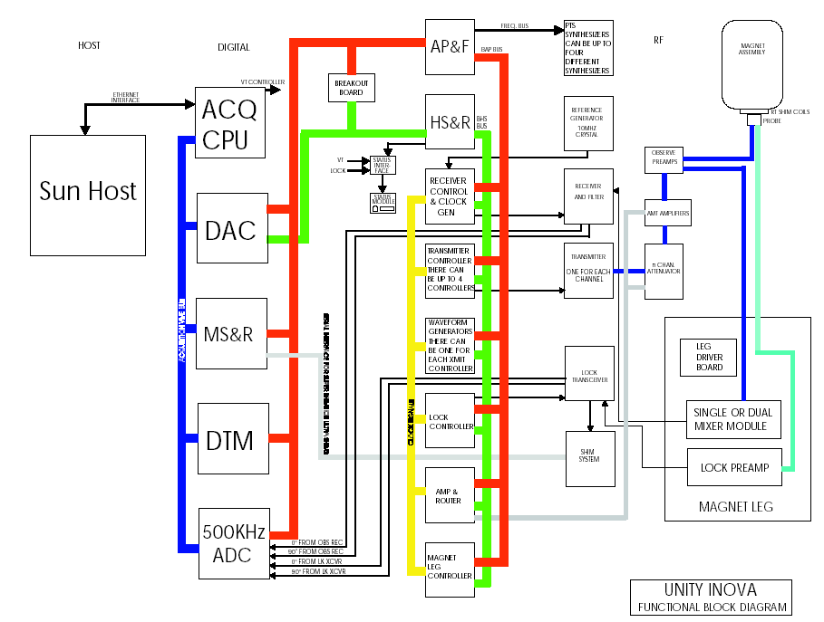
INOVA system Diagram:
Displayed Spectra is noise only, No peaks

Perform the follow procedures if you take an acquisition and your resulting
spectra shows noise only.
- Check to see if you can lock and shim your sample. If there is no lock
signal return to the section for troubleshooting the Lock Path.
- If you have a lock signal then you should change your tn to the
another band. For example, if you took a proton acquisition and your spectrum
showed noise only then change your tn='C13' or setup your standard C13
parameters and take a spectra using a sample that you know will have C13 peaks
(Use the C13 sensitivity sample). If you have lost only one band then that is
usually an indication of a switching or amplifier problem. If you do not have
peaks with either nuclei procede to the next step.
- The next step would be to measure your transmitter pulses at the probe
input. Depending on what frequency system that you have will determine what
point to measure. For this explanation we will just use general test points.
Assuming that you have no spectra for either band we will setup to pulse the
probe and measure at the proton input to the probe. Setup your parameters
using the following:
- at=.1
- pw=50
- bs='n'
- dm='n'
- nt=1e6
- tn='H1'
- tpwr=63
Connect a cable through a 30db attenuator from your o-scope to the probe
output of your preamp. start the acquisition by type go from the VNMR
command line (if you have switching relays in your magnet leg you will want
to check for pulses at the cable that connects directly to your probe).
- Set your o-scope time base so that you can view a 50 usec pulse. the
amplitude of these pulses should be approx. 2.5 to 5 V P-P. If there are no
pulses at the probe you can assume that your problem is in the transmitter
path, procede to that section. If there are pulses at the probe, check to
ensure that you are pulsing at the correct frequency. If the frequency is
correct then you should test your receive path using signal injection.
Procede to that section
- Check the power supply DC voltages. It is possible that one of the
voltages is low or missing.
Measurement Points and Signal Levels For Troubleshooting
the Transmitter Path
If there is no transmitter signal at the probe, you will need to start to
follow the signal back or bracket the path to divide the transmit path even
further.. All signal levels are based on the transmitter power set to maximum
(tpwr=63).
Transmitter Path Measurement Points
Transmitter #1 (these signals are measured straight into the o-scope)
J2X4 Synth Input +10 dBm
J2X5 LO Output +10 dBm
J2X3 Xmittr Output +10 dBm
N Channel Attenuator
J297 Channel A Output approx. +4 dBm
J298 Channel B Output approx. +4 dBm
AMT #1
J4073 Channel A Output +12 - +17 dBm (measured through a 30 dB attenuator)
J4072 Channel B Output +24 - + 26 dBm ( measured through a 30 dB attenuator)
You should see approximately 50-55 dB of gain across the AMT amplifier. To
verify this gain you must measure both the input and output at the AMT amplifier
Receive Portion of the Lock Path
You can test the receive portion by injecting a signal at probe input of the
preamp. The injected signal must be at -75dBm and should be at your transmitter
frequency. You can use a signal generator to inject the signal or you can also
use your Transmitter #2 output (if you have a dual brodband system). Once you
have injected the signal, take an acquisition, you should observe a peak in your
spectra.
Setting up Transmitter#2 for signal injection.
Make the follow changes to your experiment setup
dn='H1'
dpwr = -16
dof = 100
dm='yyy'
dmm='c'
connect one end of a bnc cable to J297 of the N Channel Attenuator board.
Connect the other end to a variable attenuator set to 6 dB of attenuation(or use
a fixed 6 dB attenuator). Connect another bnc cable from the variable
attenuator(or fixed) to probe port of your preamp. Tke an acquisition, if you do
not observe a peak in your spectrum then you will need to inject the signal
directly into the mixer module. This input needs to be approx. -40dBm. Take
another acquisition. If you still do not see any peaks then you can inject
directly into the Observe Receiver at the system IF frequency (10.5 or 20 Mhz).
This input needs to be -10dBm or less.
|